Going with the Flow in Flame Head Design

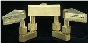
This week we continue the topic of flame head design and its importance to successful flame hardening. The shape of the design not only impacts how the part will be hardened, but so does the design of the flame ports through which the gases flow to heat the part. The way we establish a flow for a flame head is directly linked to the design of the flame head itself. Each flame head, sized and proportioned for its specific hardening coverage, takes the fuel gas and oxygen flow from a torch and distributes it through flame ports to the part. That flow of fuel gas and oxygen has to be in direct proportion to the number of flame ports and size of the head. For example, a one inch flame head has 30 flame ports. The optimal flow through each flame port is 8.75. Therefore, the total flow of mixed fuel and oxygen into the torch would be 263 Cubic Feet per Hour (CFH). Depending on the fuel gas used (natural gas, propane, propylene), there is an optimal ratio of fuel gas to oxygen that makes up the total flow. For example, in the one inch head, the optimal ratio of natural gas to oxygen is a 2:1 ratio. So you would want 176 CFH of natural gas and 87 CFH of oxygen. For propane or propylene, the optimal ratio is more like 3.5:1.
Flow control in flame hardening allows you to make small adjustments to these flow rates and ratios that can greatly effect changes in the resulting flame and case hardening. For example, by increasing the oxygen level or decreasing the fuel level from the optimal ratio, you create an oxidizing flame that burns hotter. A hotter flame heats the surface faster which allows you to create a thinner case of hardness. Any time you lessen the amount of heat absorbed in a given part, the less chance you have for excessive distortion of the steel. An oxidizing flame cone is typically shorter than a flame using the optimal ratio. Flow rates always determine the length of the flames coming out of the flame ports. That’s important to know in order to establish the coupling distance, which is the optimal distance from the surface of the part to the tip of the cone.
So you can understand how important the coupling distance is to the effective design of a consistent flame hardening solution. If you are spin or stationary hardening, you want to get the heat in as quickly as possible. If you are using progressive or combination hardening, the coupling distance and the rate of heat going into the part need to match the rate of scanning. If the flows and the scanning rate are out of sync, it will fail to heat enough to harden sufficiently, or it will get too hot and either burn, melt the surface or it will get too hot to quench out. The flame hardening solution then is a systemic one in which design considerations, starting with the end result of hardness depth and pattern, determine all the other components from application method to flame head design and quench to create the needed patterns.
To control the critical component of flow rates, Flame Treating Systems Inc. always provides a flow control cabinet with each flame hardening machine we design. The flow control cabinet uses a set of flow meters, regulators, pressure gauges, and needle control valves for both the fuel gas and the oxygen. Operators can manually set and monitor flows of gas and oxygen to prescribed levels while the machine operates automatic cycles designed to work within those levels. Customers who only want to purchase flame heads need to provide some mechanism like this at their site to achieve and then maintain the correct flow rates for the flame heads they are using. We often have to explain this concept to customers who do not understand the systemic nature of flame hardening processes and think it can only be solved with a flame head and torch.
Because the quality of the heat is such a critical component, and because you can change it by changing flow rates and the coupling distance, you must ensure the part location stays consistent in relationship to the flame head. You must always maintain the optimal coupling distance. For example, in the progressive method, if the distance between the flame head and the surface of the part changes during the scan the quality of the heat will vary. It will create either a hot spot or an area with a lower hardness level than the rest of the part. Inconsistent hardness levels obviously create potential quality issues. These issues can be controlled, but you must be aware of them to do so.
Next week we’ll explore a case where a customer came to us with process issues in their existing flame hardening equipment. There were cracking issues we had never seen before. We’ll share with you what we learned in analyzing and troubleshooting these issues in the next blog. Until then, keep your flames controlled and consistent! Email me with any requests or questions or observations. mark@flametreatingsystems.com.
B21: We would like to know your opinion.


